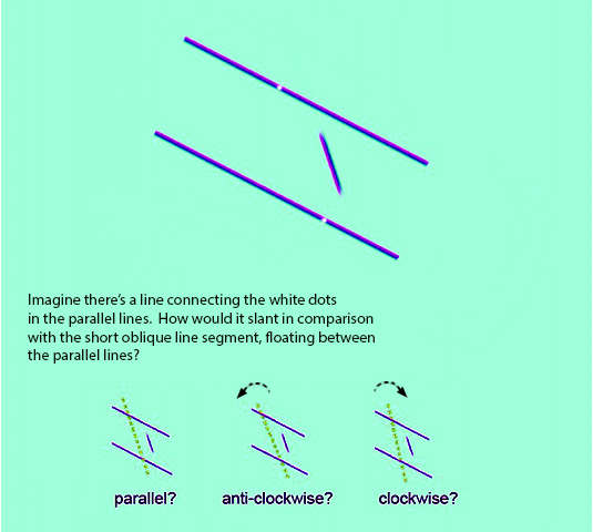
How do you see the figure above? Make a judgment before you read on!
So what’s it about?
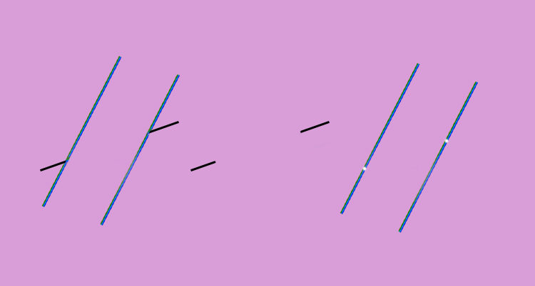
To the left above is the Poggendorff illusion. The oblique arms touching the parallels are objectively aligned, but look off-set, as if the right hand arm was shifted a bit upwards. In the centre is a variant called the Poggendorff-without-parallels. The objectively aligned line segments still look just slightly off-set, even without the parallels. So we know that at least two effects seem to be at work in the Poggendorff illusion, a small one arising even without the parallels, and an enhancing effect in some way due to them. It’s usually assumed that the enhanced effect depends on some interaction between the test arms and the parallels, and there’s evidence for that.
But now, still in the figure above, look at the figure to the right. Suppose there was a third effect at work, with the parallels but without the test arms, causing us to see the upper white dot as if shifted a little upwards – what one might call a Parallels-and-Nothing-But effect. How would we know? Without the test arms offering alignment as a tell-tale, we can’t tell.
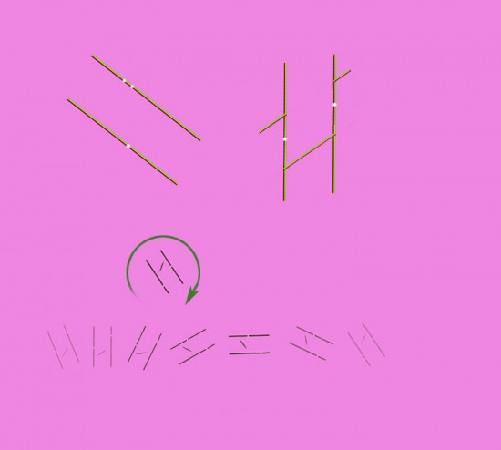
However, look at an illusion noticed half a century ago by Samuel Tolanski, shown upper left in the figure above. In the figure, the mid-point between the two little dots on the upper parallel line is objectively vertically above the single dot on the lower line, but the upper pair of dots appear shifted a bit to the left. So the vertical track from lower to upper dots is rotated anti-clockwise.
Now that could be an illusion that only involves our judgment of cardinal (vertical and horizontal) axes . But what if in fact it’s the effect described in the previous paragraph – a misjudgment of the slope between dots on parallel lines that happens at other orientations, but that is only noticeable when it conflicts with our very precise capacity to judge horizontal and vertical trajectories?
There’s one other tell-tale we can use, comparisons of slope.
In 1998 Barbara Gillam published (see her fig 28 on page 129 in that link) a figure like the one upper right, in which the slope of the track between the dots can be compared with the slope of a real oblique line. In her figure, the track between the dots is objectively parallel to the oblique line below it. However, it can look to some observers as if the right hand dot is shifted just a little upwards. So, the track between the dots appears parallel, not to the obique line below it, but instead to the traverse across the gap between the Poggendorff test arms just above it. Barbara Gillam only discussed the effect as it arises between vertical and horizontal parallels. But is the figure at the start of this post telling us that the effect remains when the parallels are rotated to oblique orientations?
This is a hard effect to study, because our judgment of the slope of oblique lines is much less acute than are our judgments of alignment or of vertical and horizontal. Also, there are other, technical reasons (details below) why slope is remarkably tricky to test. And then, testing required several hundred trials, with the figure at various orientations rotated through 180 degrees. That’s far too many to ask friends to help with, so I could only use myself as an observer – a process with obvious pitfalls.
Still, in summary, my measurements suggested that the parallel lines do indeed affect judgments of oblique transits just between target dots, varying systematically (but interestingly) with rotation of the parallels. But then when I informally tried to repeat the results in a few sample tests with friends as observers, it didn’t come out the same at all. So now I’m wondering, is there nothing in the idea, and my results just show why we can’t rely on self administered experiments in this field? Or might the idea be OK, but hard to demonstrate because of the difficulty of making slope comparisons? They are much less apparent than are the misalignments of test segments that reveal the classic Poggendorff illusion, or the departures from vertical and horizontal on which the Tolanski illusion described above depends.
Apologies for the details that follow! They will not be for everyone … But for those who have a technical interest, here are the full details of my own experiments:
As mentioned, observing the effect is tricky firstly because comparisons of slope are much less salient than the judgments of alignment that are involved in the Poggendorff illusion, or of cardinal axes, as in the Tolansky illusion. But even more of a problem, the experiments are tricky because of interference from other illusion effects.
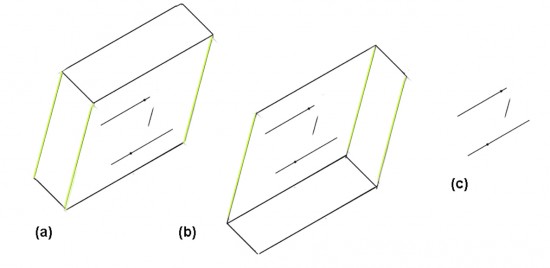
In her version of the figure, (see above), Barbara Gillam discusses the possible compromising effect of the Muller-Lyer illusion. That was avoided in my experiments by using only a short oblique line segment, which does not connect with the parallels. A harder problem was the size constancy effect. This can give rise to apparent divergence of parallel lines with distance, when a pair of oblique parallel lines is seen as receding into depth. In my trials, a size-constancy effect did indeed turn out in preliminary tests to affect slope comparisons between my oblique comparison line and the objectively parallel track between target dots, if the comparison line and track were well separated. I therefore subsequently kept the oblique comparison line close to the track between dots, which eliminated the effect. That is confirmed in this figure:
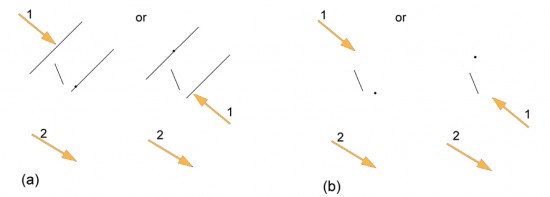
Note that there is a bit of size-constancy divergence in the (objectively parallel) yellow outer edge lines of the blocks, so that their far ends seem a touch further apart than their near ends, downwards at (a) and upwards at (b). At (a), I see divergence in the same direction between the short comparison oblique and the track between target dots. However I’m confident the divergence is not due to size constancy effects because of figure (b). In this the divergence between the test oblique segment and the track between dots looks to me just the same as in (a), but now it opposes the divergence I see in the now upward sloping edges of the figure. So it must be some effect not only not due to size-constancy, but quite unaffected by it. And in fact it looks to me identical to appearances at (c), with no spatial direction defined at all.
However keeping the oblique comparison line close to the track between dots exposed the oblique to another illusion effect, possible induced orientation effects due to the parallels. These are effects that can arise when lines at different orientations, (in this case the floating line segment and the parallels) join, or nearly join: the angle between them can appear greater than it is. The slope of the floating comparison line here could therefore potentially be affected by the parallels. The effect could be big enough to interfere with the slope comparisons in my trials. To test for that, for every orientation of the floating oblique line, I included a judgment of alignment with an isolated target dot a little way away, both with and without parallels. The point of that was that it is well known that we misjudge alignments like that without parallels, but excellent experimental data for the variation with orientation of the floating oblique is available in the literature. What I needed to do, therefore, was first to check that without parallels my measurements agreed with those in the literature, and then to see whether adding the parallels made any difference. (Answers below!)
My final test figures therefore consisted either of parallels and a short comparison oblique at angles of 22.5o, 45o or 60o from normal to parallels; or of an isolated oblique and a given test dot at equivalent positions. Each test imposed two dot placement tasks. Task (1) was either, as at (a), to place a dot on one of the parallels so that the track from a given dot on the other parallel appeared parallel to the test oblique; or as at (b), to perform an equivalent dot placement in the absence of parallels. The choice of the parallel (or equivalent position) on which to place the given dot was informally varied. Task (2) was to place a dot apparently in alignment with the test oblique, at a distance of about 3 times the length of the oblique.
Each figure, with or without parallels, was presented four times, reflected and rotated as in this figure.
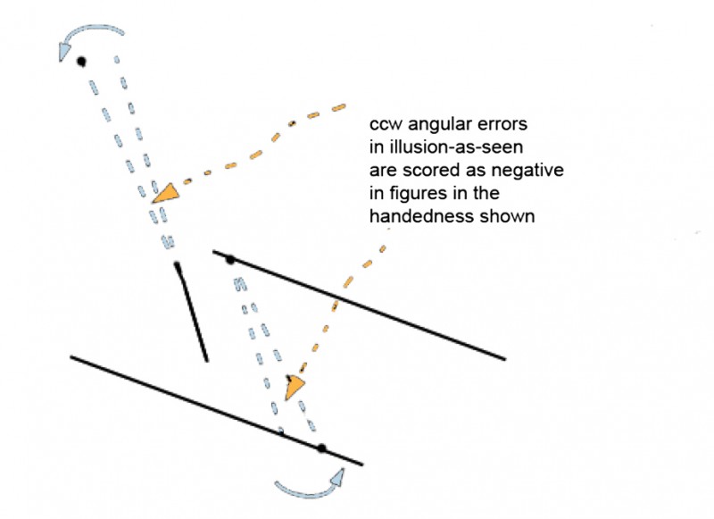
Angles of error were as shown in the figure below, scored for consistency with citation data, but this introduces another complication. Method-of-adjustment errors, like the ones I measures, are in the opposite direction to illusion-as-seen, because they compensate for error as seen. The errors I measured were therefore sign reversed. And then, scores for figures flipped vertically or horizontally were sign reversed again to preserve consistency across handedness. Trials were done in batches in informally randomized sequence, with every effort to observe normal good practice.
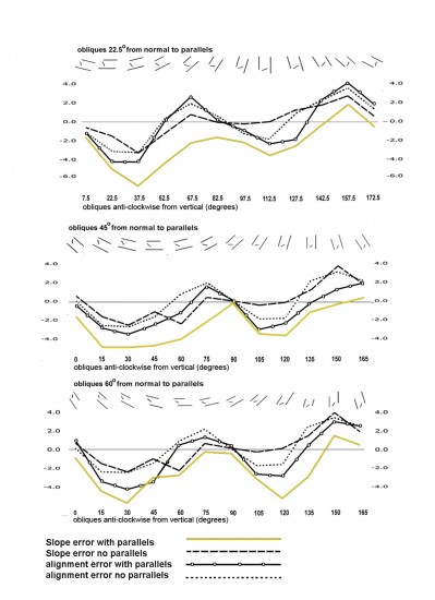
Figures were presented at 12 orientations, so that comparison obliques were rotated through 180 degrees at 15 degree intervals, as shown above the graphs of results which follow. Figures with 22.5o and 45o test obliques were presented with and without parallels. For 60o obliques, only the slope comparison tests were done both with and without parallels, since alignment tests with 45o obliques without parallels provided figures for all the orientations required.
These were the results.
1 My scores for line and dot alignment without parallels are high but otherwise comparable with line and dot alignment data from (see the references at the end) Bouma and Andriesen (1968 their figure 3); Weintraub and Brown 1986 (their figure 6); and Ninio and O’Regan (1999 their figure 5). All these studies identified an effect from cardinal axes yielding maxima in their data when test arms were about halfway between cardinal and 45 o orientations. I interpret this as rotating tracks rather than test lines, and away from the nearest axis. Puzzlingly, Greene et al. (2000) did not find this cardinal axis effect, yet it seems present in my data, including, interestingly, in the slope comparisons even without parallels.
2 Results for alignment tests with parallels are symmetric about the zero line for obliques at 22.5o from normal to parallels, but drop increasingly into negative territory for 45 o and 60 o obliques, suggesting a small effect of assimilation of the comparison oblique towards the orientation of the parallels at the larger angles.
3 However scores for the critical test, of track slope errors with parallel inducers, do still show a clear additional shift into negative territory, arguably indicating the track assimilation effect sought.
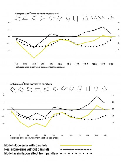
4 We can model the results quite well by summing our real graphs for slope error without parallels with a model effect of track assimilation towards parallels, at a maximum whenever the track is at 45 o from cardinal orientations.
Those results are quite self-consistent, and do suggest that for me at least there is an effect from the parallels on judgments of an oblique traverse between them.
However, as mentioned above, when I tried sample tests to confirm my results on some friends, it didn’t work out! Either I’m seeing things, or else these judgments of slope are very difficult, but I’ve unintentionally got to be rather accurate with them by practice, and only many tests on a huge sample of observers would show the same pattern.
References
Bouma H, Andriesen J J, 1968 “Perceived orientation of isolated line segments” Vision research 8 493-507
Gillam G, 1998 “Illusions at century’s end” in J Hochberg Ed, Perception and Cognition at Century’s End (London: Academic Press) pp 93 – 136
Greene E, Frawley W, Swimm R, 2000 “Individual differences in collinearity judgment as a function of angular position” Perception and Psychophysics 62 (7) 1440-1458
Ninio J, O’Regan J K, 1999 “Characterisation of the misalignment and misangulation components of the Poggendorff and corner-Poggendorff illusions” Perception 28 949-964
Weintraub D J, Brown S, 1986 “Perceptual plane geometry: collinearity judgments probe the perceived orientation of an angle’s sides” Journal of Experimental Psychology 12 (4) 434-444


the parallel lines appears to be anti-clockwise.
great site